
What is a construction drawing?
A construction drawing or set of construction drawings form part of the pre-construction information that is used to construct a building. Before we dive in to construction drawings, what they look like and what they include – lets take a step back and look at the process as a whole.

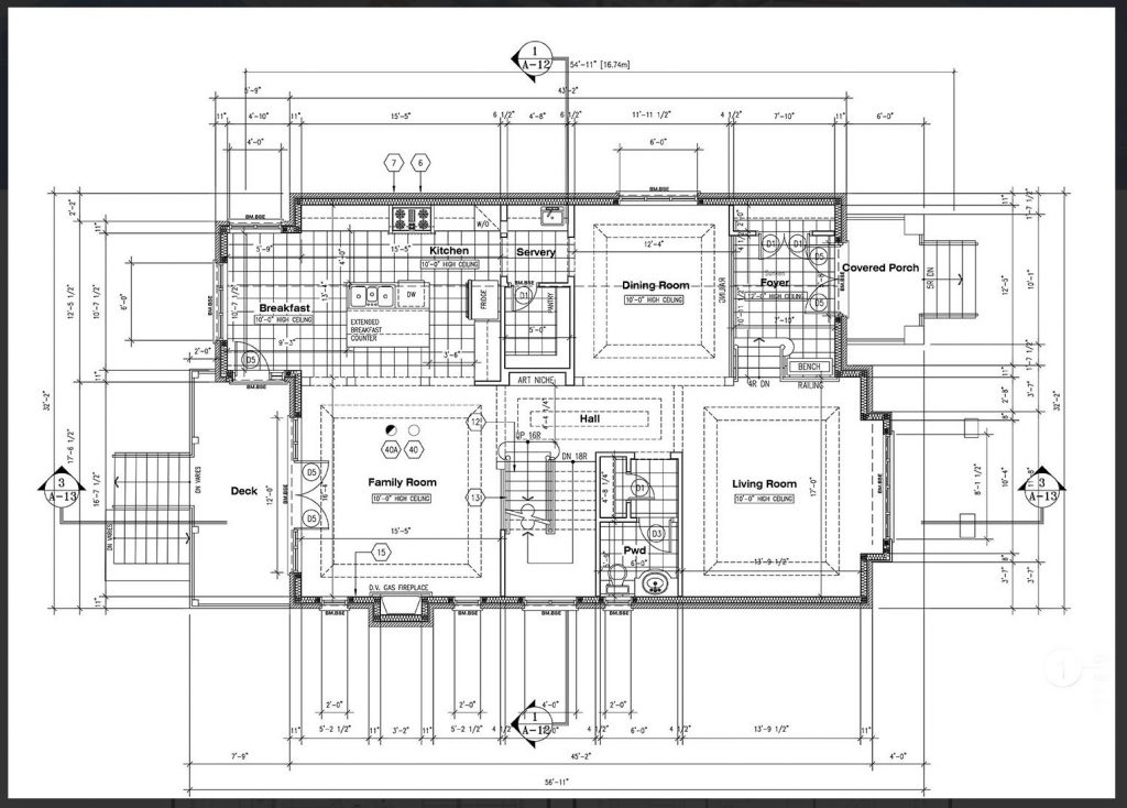
AD-01 House – Diaz Fernandez Arquitectos
Architectural drawings in the design process
Architectural drawings play a key part of the design and build process from start to finish. At every stage of the design there will be a set of drawings that represent each design stage. In the early part of the process, the architectural drawings will be more simple, general and will not contain large amounts of detail. Initial sketch drawings will be used to develop ideas and start the design of the building.
When it is time to apply for planning permission from the local authority, planning drawings will be prepared that show the planning department the intention of the design. Planning drawings will contain more detail and give a representation of the buildings location on site, size, form, and many other factors that are relevant to the planning department.
After the plans have been approved by the local authority, detail design or technical design stage commences where construction drawings will be prepared, both for tender documentation and for the build itself.
What are Construction Drawings?
Construction drawings form part of the overall documentation that is used for tender, for the contract between the employer and contractor, and for the construction itself.
The construction drawing provides a graphic representation of how the building will be built. They will be as clear as possible, and easy for the construction team to read. It is vital that the drawings do not lead to any misunderstandings which could cause errors or delays.
Construction drawings are usually accompanied by a specification document. Specifications detail all the materials, techniques and standards that must be adhered to in order to construct the building.
Depending on the project, a construction drawing will sometimes detail some of the specification information, but in other cases the two will remain separate. It is usually best to keep the two separate in order to avoid mistakes when one item is updated in the specification but then missed in the drawing or visa versa.
Construction drawings often include information from other specialists, for example structural engineers, HVAC (heating, ventilation and air conditioning), electrical and fire safety. Again, the level of information and amount of external collaboration will depend on the size of the project. On a small residential project many of these aspects will be covered by the architect, however on larger projects there may be a number of external professionals who play their part in the overall production of construction drawings.
All of these different drawings make up a thorough representation of the building in order to allow it to be constructed correctly (or tendered).
What is included in a set of architectural construction drawings?
A set of construction drawings usually contains the following drawings at scale:
- Floor/roof plans – a GA (general arrangement) drawing will give an overview of the building plan
- Elevations – these give information on the external finishes, windows, and so on although most detailed information will be in the plans and sections, the elevations tend to be more of a visual aid.
- Sections – show the construction of the walls and floors along with heights, levels etc.
- Details of specific parts of construction – usually connections and junctions and any other areas that will need attention, windows for example or change in materials etc.
- Window/door schedules – listing the windows and doors, with all associated information (this is sometimes listed as a text document, and sometimes a drawing showing each window style, size, information etc.)
Other drawings include (depending on project):
- External works and drainage plan
- Landscaping plans
- Furniture plan
- Reflected ceiling plan
At this stage of the process it is clear to see the benefits of BIM, where working with a 3D model to create a range of views makes it easy to produce the information required. It also has the benefit of reducing time spent on amendments. In a BIM model, if an element is changed, this will be reflected in all of the different views, rather than having to go in manually and change each floor plan, elevation, section etc. Other standard CAD applications are unable to do this.
What information is in a construction drawing?
Construction drawings are used to construct the building, so it is important they contain everything the contractor needs to build.
This will include information such as structural layout or grid, dimensions, clear labelling of elements. To give an idea of the general requirements of construction drawings, the list below looks at each type of drawing and what will usually be included. This is not an exhaustive list, so if there is anything you would like to add just drop me an email or please comment below!
Floor Plan Construction Drawing
- Names of rooms
- Scale
- Dimensions
- Size and build up of both external and internal walls and partitions (sometime a key/legend is used for this)
- Location of any structural elements such as beams, columns, lintels, etc
- Stair information and direction
- Any references to section lines and detail drawings
- Material details, specifications or notes
- Heating and ventilation details (could be a separate drawing)
- Electrical information (could be a separate drawing)
- Water and drainage information
- Fire safety information
- Building levels (finished floor level, external ground level etc)
Tesla Outsourcing
AD-01 House – Diaz Fernandez Arquitectos
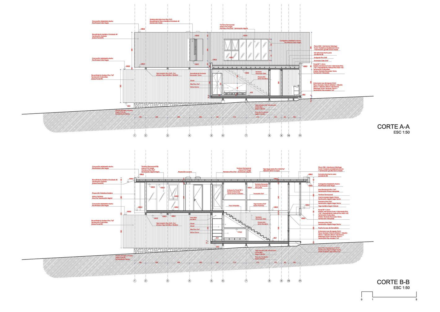
Elevation Construction Drawing
- Scale of drawing
- Dimensions
- Finished floor levels and external ground level
- Claddings, finishes etc
- Roof shape, slope and materials

AD-01 House – Diaz Fernandez Arquitectos
Sectional Construction Drawing
- Scale
- Dimensions
- Size and build up of both external and internal walls and partitions (sometime a key/legend is used for this)
- Location of any structural elements such as beams, columns, lintels, etc
- Stair information if applicable
- Any references to detail drawings
- Material details, specifications or notes
- Heating and ventilation details if applicable (could be a separate drawing)
- Electrical information if applicable (could be a separate drawing)
- Fire safety information
- Building levels (finished floor level, external ground level etc)
- Foundation information
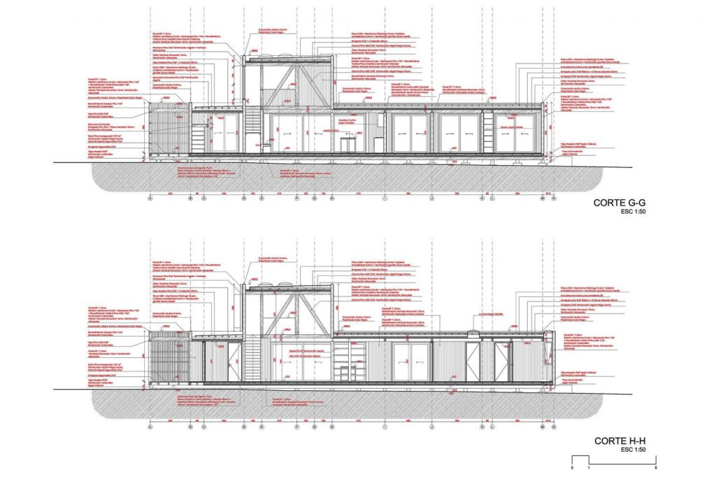
AD-01 House – Diaz Fernandez Arquitectos


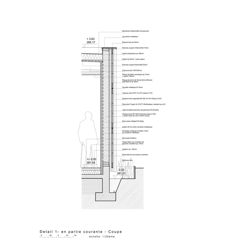
Detail Drawings
Detail drawings usually at a scale of around 1:20, 1:10 depending on the project and information. These will demonstrate junctions, complex parts of the build, typical details and anything else that will assist the contractor in executing the build effectively.


Obviously there is a lot of information contained in the construction documentation and this article gives an overview of what the detailed design stage looks like. Every project is different and must be treated accordingly. You know I always love to get feedback from you guys so if you have anything you would like to add to the above, please feel free to comment below. I would love to hear your thoughts.
If you work in practice and would like to share some of your construction drawings we would be delighted to feature them. Please drop me an email – emma@firstinarchitecture.co.uk


Need help with setting up your AutoCAD? We have a template that comes with all the layouts, layers, cad blocks to help get you started, along with dimension styles and so much more. It is a great way to look professional right from the start.
Image Credits:
AD-01 House Diaz Fernandez Arquitectos – https://www.archdaily.com/910032/ad-01-house-diaz-fernandez-arquitectos?ad_medium=gallery
Tesla Outsourcing – https://www.teslaoutsourcingservices.com/architectural-construction-drawings-samples.php
Welcome Centre by Ventura and Llimona – https://www.archdaily.com/775213/interpretation-and-welcome-center-for-visitors-in-la-antigua-ventura-plus-llimona?ad_medium=gallery
Nursing Home Extension by Studiolada – https://www.archdaily.com/923858/nursing-home-extension-studiolada?ad_medium=gallery


Great explanation. Design is the most important part, if you get it right, everything else will follow.
Thank you Geri.
伟大的介绍construction drawings and their value in the digital construction workflow. I would add that if planning an extension or a refurbishment, it’s a great idea to get 3D scans of as-built data to inform your construction drawings, so you know your drawings are based on what’s actually in the ground already.
I am architecture student. I was lost in understanding what exactly
The college is teaching. Education is simplicity and I found that from your educational materials you have. Please contact me and with you direct company address email so I will enrol
我有这么好的使用CMS IntelliC的经验AD and find it to be one of the best CAD software out there. It was so easy for me to start working with it as it offers all the CAD tools that I am aware of to understand whether it’s worth it, and the special offer by CMS came as a nice surprise. Definitely recommended on my part! ready familiar with. I got a free trial right upon registration. It was great as I was able to work with the software.
As a hobbyist, I’ve tried various CAD software before I came across CADHOBBY IntelliCAD. It’s the best software that suits my needs as a beginner in 3D design.
https://www.cadhobby.com/